Choosing an Interlocking Intramedullary Nail is not a catalog exercise. The right system must fit the fracture, the bone, and the surgeon’s planned technique. A femoral shaft fracture with a wide canal may call for different considerations than a short, unstable tibial fracture. Nail diameter, length, locking options, insertion instruments, and imaging access all matter. Small details matter.
Prof. Peter V. Giannoudis is a recognized orthopedic trauma researcher whose work addresses fracture fixation and healing. A concise paraphrase of the clinical principle reflected in this field is: “Choose fixation to suit the fracture and patient, not the implant alone.” This is a paraphrase, not a verified direct quotation. That distinction matters when clinical guidance is presented.
This guide explains how to compare nail designs and assess their practical trade-offs. It considers fracture location, canal anatomy, locking configuration, material, and available instrumentation. It also asks what product documentation can actually establish: dimensions, indications, compatibility, and testing details. A polished brochure is not enough. Review current instructions for use, confirm local availability, and discuss the choice with qualified orthopedic professionals. No single nail is right for every case. And product selection alone cannot guarantee healing; patient factors, surgical technique, and follow-up also shape outcomes. Some comparisons remain difficult because manufacturers may report performance differently. A careful buyer should admit that uncertainty, rather than mistake a neat table for clinical proof.
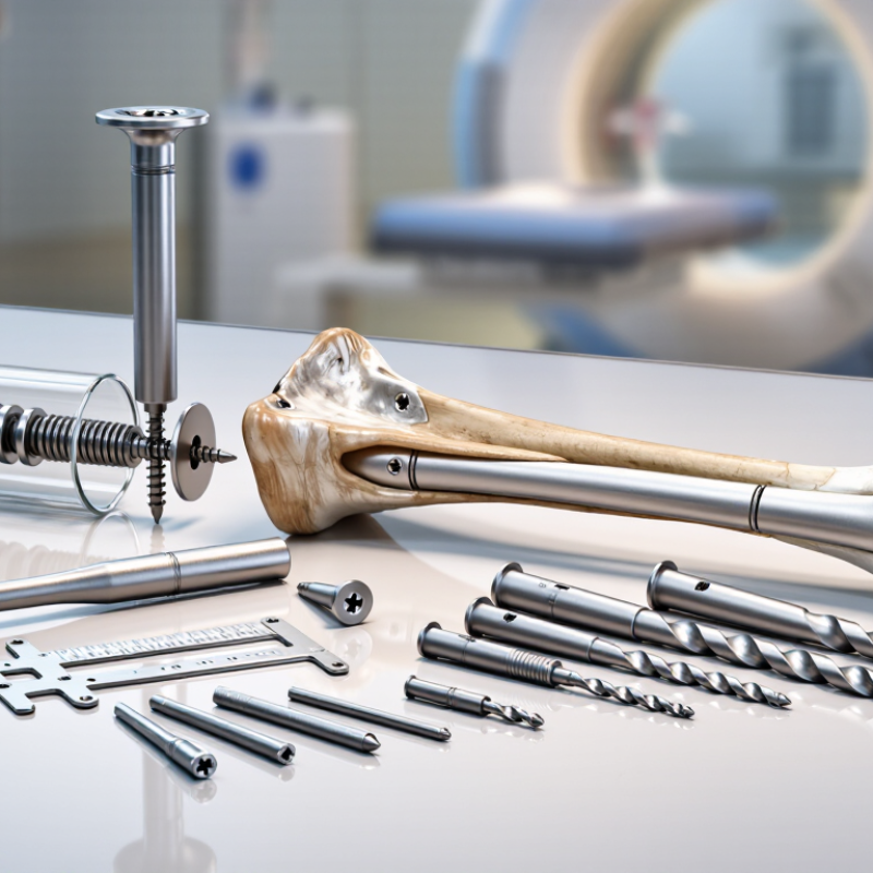
Choosing an interlocking intramedullary nail starts with the fracture’s location. A midshaft fracture may need a long nail with secure locking above and below the break. Distal or proximal fractures need enough fixation points near the bone end. Check the nail’s curvature, length, and locking options against the patient’s anatomy and imaging.
Pattern changes the choice. A simple transverse fracture differs mechanically from a short oblique, comminuted, or segmental break. The AAOS 2021 Clinical Practice Guideline supports cephalomedullary nails for unstable intertrochanteric, reverse-obliquity, and subtrochanteric fractures; stable intertrochanteric fractures may suit either a nail or sliding hip screw. That distinction matters. A tidy fracture label can still miss a small fragment or poor cortical contact, so review the images in more than one view. Nail choice alone cannot compensate for weak reduction or inadequate fixation.
Tips: Match locking options to the fracture level and expected rotational forces. Confirm that the planned nail fits the canal and curvature. Small details matter. When stability remains uncertain, reassess reduction quality and bone support with the treating orthopedic team.
Choosing an interlocking intramedullary nail starts with careful measurements, not guesswork. Estimate nail length on calibrated imaging, from the planned entry point to the intended distal position. Check the opposite side when appropriate, but do not assume both bones match exactly. Fracture alignment and limb position can change the apparent length. Confirm measurements during surgery with imaging.
Measure canal diameter at its narrowest point, often near the isthmus. If reaming is planned, account for the final reamed canal size: the selected nail is commonly about 1–1.5 mm smaller than that diameter. This is a planning guide, not a universal rule. Bone quality, fracture pattern, implant design, and surgical technique can change the choice. A small measurement error matters. Recheck calibration and sizing before insertion.
Tips: Keep the limb in a consistent position when measuring. Compare several views, and verify nail length with an imaging guide. If the numbers conflict, pause and reassess; an imperfect image can create false confidence. Follow the device instructions and the treating surgeon’s judgment.
Choosing an interlocking intramedullary nail involves more than checking its diameter and locking-hole layout. The alloy standard offers a useful starting point. ASTM F136 covers wrought titanium-6aluminum-4vanadium ELI alloy, while ASTM F138 covers wrought implant-grade stainless steel. F136 sets requirements for composition and material properties; F138 does the same for its specified chromium-nickel-molybdenum steel. These standards help buyers and clinical teams compare documented material specifications, not predict the performance of every finished nail.
Titanium alloy is less dense than stainless steel and may create less imaging artifact, though scan results depend on the implant’s shape and imaging method. Stainless steel has a long record in orthopedic implants and may suit systems designed around its mechanical characteristics. Neither alloy is automatically the better choice. A standards label is not the whole story. Review the device’s fatigue data, dimensions, locking-screw compatibility, surface condition, and instructions for use.
Ask whether the documentation identifies the exact alloy and applicable standard, rather than relying on a general “medical grade” claim. Small details matter. The standard does not verify a nail’s design or clinical fit, and that distinction is easy to overlook. Teams should weigh those details alongside the patient’s anatomy, fracture pattern, and the treating surgeon’s judgment.
Static or dynamic locking changes how an interlocking nail controls movement at the fracture. Static locking uses screws at both ends to limit shortening and rotation. It is often considered for comminuted or length-unstable fractures, where bone ends cannot reliably support each other. Dynamic locking allows controlled axial movement through a slot. In a simple fracture with good cortical contact, this may encourage compression during weight-bearing. Too much movement, however, can lead to shortening or deformity.
The scale of fracture care is substantial: the Global Burden of Disease 2019 study estimated 178 million new fractures worldwide. That figure describes all fractures, not nail-treated injuries, but it underlines why careful fixation choices matter. Assess the fracture pattern, reduction, bone quality, and expected loading together. A clean X-ray can still hide rotational instability. And “dynamic” is not automatically better. Surgeons may also begin with static locking and consider dynamization later, based on healing and clinical findings.
Tips: Check whether the fracture can maintain length and rotation before choosing a dynamic slot. Confirm screw position on imaging, and reassess alignment during follow-up. Small details matter. Evidence does not support one locking mode for every fracture; the choice should match the patient and fracture, not habit alone.
A useful interlocking nail must match the fracture pattern and the planned screw paths. Review the proximal and distal locking options against the patient’s anatomy and the intended reduction. A screw that appears well placed on one image may cross a joint or miss the desired bone corridor in another view. Small details matter.
Check the instrument set before surgery. Targeting guides, drill sleeves, and depth gauges should fit the nail system securely, with no unexpected play. Confirm that the available screw lengths and diameters match the implant specifications. A dry-run assembly can reveal alignment problems early. It is easy to assume compatible parts will work together; that assumption deserves a second look.
Imaging visibility also affects accurate placement. Assess whether the nail and locking holes can be identified clearly under the imaging method used by the surgical team. Metallic overlap, patient positioning, and fracture location can make a target harder to see. Plan for orthogonal views, and verify each guidewire and screw position before advancing. Check the fit. Follow the device instructions and local clinical protocols, and involve trained orthopedic professionals in implant selection and placement.
| Selection dimension | Common design options | What to verify | Why it matters |
|---|---|---|---|
| Proximal screw trajectories | One or more fixed or selectable trajectories; some designs offer different directions for particular anatomical regions. | Confirm the available paths on the implant’s planning images and whether the intended screw positions can be achieved for the fracture pattern and anatomy. | Trajectory affects where fixation can be placed and whether screws can avoid unwanted joint penetration or interference with other implants. |
| Distal interlocking options | Static locking, dynamic locking through a slot, or a combination of locking-hole options, depending on the nail design. | Check the location and orientation of each hole or slot, and confirm which options are permitted for the selected nail length. | Locking configuration influences control of rotation and length; the appropriate construct depends on the fracture and the treating surgeon’s plan. |
| Screw and nail dimensions | System-specific ranges of nail diameters, lengths, and compatible locking-screw sizes. | Review the manufacturer’s current sizing and compatibility documentation. Do not assume that screws from different systems are interchangeable. | Correctly matched components and appropriate sizing are essential for assembly and intended fixation. |
| Targeting instruments | Proximal targeting arms, drill sleeves, depth gauges, and either guided or fluoroscopy-assisted distal targeting methods. | Verify that the targeting arm and sleeves correspond to the exact nail model, side, and configuration being used. | Instrument fit and alignment affect the ability to target the intended holes and can help avoid unnecessary repositioning. |
| Instrument compatibility | Dedicated insertion handles, connectors, guide wires, reamers, and extraction tools are typically specified for a particular system. | Check the complete instrument list, connection types, and any required accessories before the procedure; confirm availability of extraction instruments if needed. | Compatibility should be verified from system-specific documentation rather than inferred from similar appearance or dimensions. |
| Imaging visibility | Metal implants are visible on radiographs; visibility and image appearance vary with material, geometry, and imaging conditions. | Review representative radiographs or technical documentation and confirm that the nail and locking holes can be identified with the planned imaging setup. | Clear visualization supports assessment of nail position, screw placement, and locking-hole alignment during imaging-guided work. |
| Fluoroscopy and targeting workflow | Distal locking may use freehand fluoroscopic targeting or a system-specific targeting method. | Confirm the required imaging equipment, access to the operative site, and the steps described in the applicable technique guide. | The workflow influences equipment preparation and may affect the time and imaging required to locate and target locking holes. |
| Material and MRI information | Implants may use different metallic materials. MRI conditions and labeling are product-specific. | Check the implant’s material information and current MRI safety labeling; do not infer MRI conditions from the general implant category. | Accurate material and MRI information is important for documentation and for later imaging decisions. |
| Technique documentation | System-specific surgical technique guides describe indications, component combinations, instrumentation, and procedural steps. | Use the current instructions for the exact implant configuration and verify any limits or contraindications with the responsible clinical team. | Design features and permitted combinations differ among systems, so the applicable documentation is the definitive compatibility reference. |
Note: This comparison summarizes general selection considerations, not a recommendation for a particular patient or fracture. Implant choice, locking configuration, and imaging workflow should be determined by qualified clinicians using the current system-specific instructions for use and surgical technique guide.
F136 covers wrought titanium-6aluminum-4vanadium ELI alloy. F138 covers wrought implant-grade stainless steel. Both specify material requirements.
No. It documents material specifications, not the finished nail’s design or clinical fit. I might overlook that distinction when comparing labels.
Titanium is less dense and may create less imaging artifact. Results still depend on implant shape and imaging method.
Check fatigue data, dimensions, locking-screw compatibility, surface condition, and instructions for use. Confirm the exact alloy and applicable standard.
Static locking uses screws at both ends to limit shortening and rotation. It is often considered for comminuted or length-unstable fractures.
A slot allows controlled axial movement. With a simple fracture and good cortical contact, movement may encourage compression during weight-bearing. Not always.
Excessive movement may cause shortening or deformity. Check whether the fracture can maintain length and rotation before choosing a dynamic slot.
A surgeon may begin with static locking and consider dynamization later, based on healing and clinical findings. Follow-up imaging helps reassess alignment.
No. A clean X-ray can still hide rotational instability. Assess fracture pattern, reduction, bone quality, and expected loading together.
No single mode fits every fracture. The choice should reflect the patient and fracture, with the treating surgeon’s judgment guiding care. Small details matter.
Choosing an Interlocking Intramedullary Nail begins with matching its design to the fracture’s location, pattern, and stability requirements. Consider whether the nail provides appropriate length, curvature, and locking options for the bone and fracture configuration. Measure the medullary canal carefully, then account for a suitable reaming allowance of approximately 1–1.5 mm when determining the nail diameter. These measurements help support proper fit while preserving room for insertion.
Compare material options by reviewing applicable standards, including ASTM F136 for titanium alloy and ASTM F138 for stainless steel. Select static or dynamic locking according to the desired control of axial movement and rotation. Before use, also verify that screw trajectories suit the intended fixation, that instruments are compatible with the implant, and that imaging visibility is adequate for placement and assessment. A systematic review of these factors can help guide an informed choice while keeping fracture-specific needs at the center of planning.